SBS Answers
Answers to frequently asked questions about SBS.
Automated Utility Design™

What is AUD?
AUD is a leading utility distribution design tool based on the industry-standard AutoCAD platform. AUD provides a structured, user-friendly environment for automating the detailed design of distribution utility assets within a safe and effective network construction. Designs can be swiftly laid out based on an organization’s design standards and business rules. AUD supports projects ranging from simple maintenance work orders to large, highly engineered capital projects. AUD’s extensive features include automating the following processes:
· Reports
· Bill of materials
· Cost estimates
· Feature placement
· Construction documentation, callouts, schedules, and details
Automating these common design processes ensures consistent, accurate, and efficient designs while minimizing costly change management, training, and support expenses.
How is validation handled in AUD?
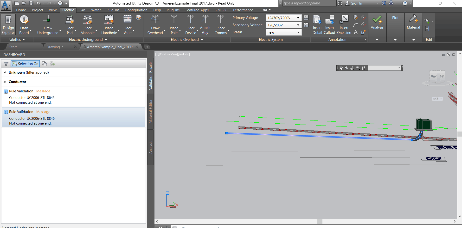
As a feature in the design is manipulated (created, deleted, or modified) by the designer, the rules validate that the action taken is within the utility’s standards. If the action violates standards, one of two possible actions can occur depending on the designer’s preference. If possible, AUD will replace the feature with a new component that meets standards (e.g. increase duct size, upsize transformer, add elbow). If no option is available (e.g. a conductor is unconnected on one end), a visual and textual validation error is provided. The user can click on the error notification, and the location of the design issue will be highlighted in the drawing.
Example of a validation error
Does AUD have the ability to validate design material compatibility or connectivity, and how does it notify the user?
Yes, AUD validates design material compatibility and connectivity. Design validation rules are configured in the template to check the design against standards. Validation errors and warnings are presented to the designer in the “Validation Tab” of the AUD dashboard and as special symbols attached to a feature in 2D and 3D view. If desired, the user can open and review the configured rule that detected the validation. The user will be provided with the option to auto-resolve the validation. This helps the designer to understand errors and resolve them using the provided auto-resolution mechanisms. The diagram below shows details of connectivity for a gas valve.
What are AUD data import capabilities?
AUD includes the ability to import, interrogate, and manipulate all file formats supported by the version of Map 3D that is hosting AUD. (Supported file formats can be found here.) In addition to the ability to import file formats, AUD has full access to the core Map3D Toolset Feature Data Objects (FDO) functionality. (FDO capabilities can be found on the OSGeo website.)
Once data is imported into the AUD design environment, the system includes the ability to manually convert the features from third-party documents into AUD features to include attributes and geometry. The conversion process includes inheriting attributes from the source as feature attributes and merging with the model attributes from the created AUD industry models.
What are the hardware requirements for AUD?
AUD requires the same hardware specifications as Autodesk’s AutoCAD. AutoCAD hardware specifications are shown on this page.
Does AUD support macros?
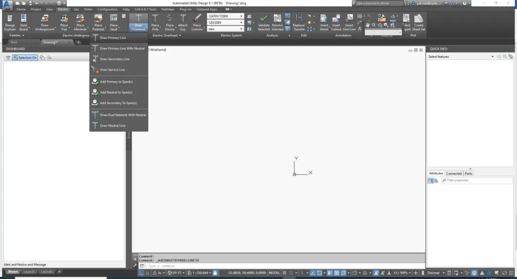
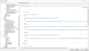
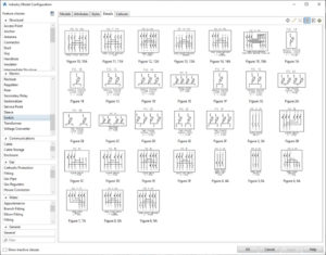
Yes. Macros can be configured to perform placement of multiple Compatible Units (CU) with a single click based on standards defined in the AUD business rules. For example, in the sample below, overhead macros are configured to create a dual circuit with a single line draw. The macro will create the poles, guys, pole tops, neutral, and circuits. All features will be placed (pole zone) according to utility standards. Validation rules will be automatically run, and sag, guying, and clearance reports will be made available.
Sample of templates for multiple CU macros
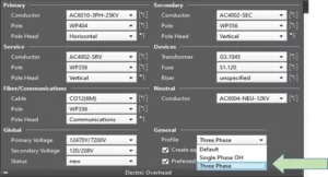
Sample of setting default CU settings based on design type
What engineering calculations does AUD perform?
AUD includes an out-of-the-box set of engineering calculations:
· Voltage drop and flicker calculations
· Underground cable pulling tension
· Overhead sag calculation for wind, ice, and temperature
· Pole sizing
· Guying
The out-of-the-box rules can be configured to a utility’s specific standards through simple interfaces. The AUD architecture of implementing the rules within the drawing template (.dwg file) allows engineering departments to implement changes to design standards without requiring code changes to AUD. The calculations assist users in correctly sizing and locating facilities based on utility standards. Engineering validation notifications enable designers to make design corrections.
AUD engineering, data validation, material ordering, stylization rules, and industry models are configured to match each utility’s design/construction standards. The rules and industry models are embedded in an AutoCAD template and enabled at the start of the design. The rules are stored with the project for the life of the project file.
How does AUD support BIM?
AUD supports Building Information Modeling (BIM) integration through our Utility DataHub™ (UDH) suite of configurable integration modules. SBS has developed integrated workflows that support the Autodesk® BIM 360™ platform. Autodesk and their BIM 360 offerings are recognized as leading products in the BIM marketplace.
BIM 360 provides:
· Cost management and workflow support
· Collaboration and constructability workflows
· Generation and management of construction submittals and packages
· Document management
· Quality management, coordination, and constructability
· Project management
· Data analytics
· 3D visualization
UDH provides a service-based interface to BIM 360, offering an alternative to design drawing management via the BIM 360 Docs product.
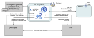
An architecture diagram
Does SBS support ArcGIS Workflow Manager and similar Workflow Management Tools?
Organizations using AUD may select the workflow management platform of their choice, including ArcGIS Workflow. Any platform that supports integration points via interface tables, REST, or SOAP APIs can be configured via SBS Utility DataHub™ to allow AUD designers to view the assigned work orders, view and update job status, and provide access to approval workflows. Once the AUD design package is visualized within the ArcGIS Pro using SBS’s plug-in, the capabilities of ArcGIS Workflow Manager can be used to manage workflows internal to the GIS requirements.
How does AUD handle simple jobs?
AUD has extensive capabilities for creating large, very advanced utility infrastructure designs, but AUD is also exceptionally productive when performing simple, repeatable design jobs.
Below are some examples of things that can be automated when working with AUD to streamline the design of simple jobs:
· Linking the Work Request to a design in the Work Order Browser
· Selecting the correct predefined template(s) when linking
· Navigating to the geographic location where the work is to be performed
· Setting the work order boundary
· Importing the landbase and infrastructure assets from Geographic Information Systems (GIS)
How is it done?
AUD core capabilities provide the flexibility to support scaling for simple and multi-phase complex jobs by offering template options, project modes, and configuration controls. Utility DataHub™ (UDH) is also involved in streamlining and automating the integration of small jobs.
Utility DataHub™ Work Order Browser Ready to Generate the Basis of a Small Design
AUD can be configured to create a design from a selection of templates, each uniquely configured to optimize the design workflow for the type of work order. UDH automatically selects the correct template based on User ID, Group ID, or Work Order type.
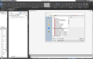
Multiple Templates Available for Design
The template for a job can include a default project mode, with the option to change modes at any point in the job. Each mode progressively enables more functions than the previous mode. For example, Estimate Mode is typically chosen for simple jobs while Analysis Mode might be used for more complex scenarios.
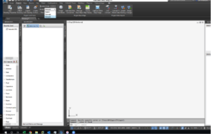
Selecting a Design Mode
UDH allows for GIS queries and automates the design steps based on manual request or Work Order type. For simple jobs not requiring reviews and signoffs, the steps to import and export design results between AUD and external systems can also be automated.
Within these options, AUD also offers a variety of configuration controls in the design and validation sessions to enable or disable functionality for job specific scenarios.
Why automate small job designs?
Many utility organizations take shortcuts for their smallest jobs to ensure that they can be processed as quickly as possible. Unfortunately, when small jobs are not properly managed, utilities typically encounter a number of challenging problems:
· Records are not updated in a timely manner, which may impact other systems such as asset management, outage management, and distribution management
· Lack of design validation may cause engineering standards to not be met
· Assets may require manual updates
· Materials management workflow is bypassed or done manually
· GIS becomes out of date, which can impact future restoration activities
Properly integrating all utility jobs into a single cohesive workflow ensures that utility organizations will have the best operational systems to provide safe utility services to their customers.
How does AUD “scale” in large, multi-region deployments?
The SBS architecture is optimal for large-scale, multi-region deployments. AUD is a plug-in to the AutoCAD® Map 3D Toolset (a desktop application). It scales horizontally by adding new desktop applications. Network connectivity requirements are minimal and are only required at the beginning and end of the design session. When network connectivity is required, the amount of information exchanged is relatively small (e.g., copying a work order and GIS information into the AUD DWG file at the start of a design). Similarly, exporting the design to the GIS and the bill of material (BOM) to EAM also requires minimal network traffic.
AUD has been deployed in a variety of architectures to support large, multi-regional utilities. This includes a single GIS schema with multiple instances and a single SAP instance. Other deployments include AUD on-premise integrated with cloud hosted SAP HANA and ArcGIS Utility Network. AUD has also been deployed using a thin-client VDI technology such as Citrix XenApp or VMWare.
AUD is enabled through the AUD template configuration. This allows a common code base to be deployed across all affiliates, with the template configured to support unique regional and regulatory design standards.
Can AUD create multiple versions of a design based on varying design assumptions? If so, how are these stored and made available to EAM and GIS?
Yes, AUD can create multiple versions of a design based on varying design assumptions with no limitation on number of versions and variations. AUD designs are created in a standard AutoCAD® DWG file. Design support data, including GIS network features and imported CAD files from external sources, are cached in a DWG file at the start of a design. This allows designers to open and alter a design based on alternative assumptions. Each alternative can be archived with a unique name (e.g. WO123_Alternative1, WO123_Alternative2). When an alternative is selected, the DWG can be opened and exported to EAM and GIS as completed.
How does AUD handle supporting documentation (CAD files, PDFs, etc.) necessary to complete the design?
As a plug-in to AutoCAD®, AUD inherits all the extensive AutoCAD capabilities to import and utilize external supporting files into the design. AUD can also leverage most document management systems to store design files, file versions, and associated documentation. This is accomplished via the use of the Utility DataHub™ – EAM module. Commonly used document management systems include Vault, ProjectWise, OpenText, and others.
How does AUD support work assignments?
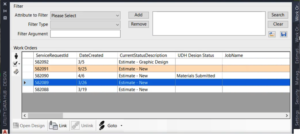
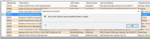
All metadata about work orders is presented to the AUD user in a single work order browser dialog. This dialog can be used for managing different work requests as well as searching and linking work orders to designs. The work order browser supports the necessary functionality of managing work requests synchronized from the utility’s work management system. Upon opening the work order browser, users see an initial filter of work requests available to them based on the different authorization credentials of the designers. The dialog also shows work request status, design status, and other pertinent information necessary to support design performance management.
Searching and filtering allows designers to query and view different work requests based on field attributes within the user authorization (e.g. search by name of a designer). The Work Request Query and Filter Designer functions can link or unlink an assigned work request to the design drawing and automate the process of storing data in the design document repository. Work order browser can be configured to check out an existing design or to extract and create a new version. This capability allows an existing design to be used as the basis for a new design. This preserves both the as-designed and as-built copies of the design. The screenshot below shows linking of work requests in the work order browser dialog.
Linking of work requests
Once a design is linked, Utility DataHub™ (UDH) will set a design status, which can provide information necessary to manage the design process. Examples of design status may include “In Design,” “Permit Pulled,” “Site Inspected,” “Ready for Review,” etc. Statuses can be shared with the work management system. The statuses can also be used to control workflows, data routing, approval processes, multi-design, partial posting to Geographic Information Systems (GIS), and bill of material (BOM) submission.
Will AUD allow the user to create custom filters for the purpose of selecting or viewing a desired set of work orders?
This function is a core capability of the Utility DataHub™ Design – EAM module. Designers can filter any combination of attributes in the work order. Quick filters can be configured for common searches. Designers can create personal custom filters saved to their personal directory that can be shared among designers.
Can AUD allow work order properties to be made available to the user for filtering purposes?
This is a core capability of Utility DataHub™ Design – EAM as well as sorting.
Does AUD have the capability of letting the user visually see what work order(s) will be processed when submitting materials and when multiple work orders have been linked into the design?
Yes, this is a core capability of AUD. The designer can link multiple work orders into a single DWG file with the CUs uniquely assigned to one work order. When submitting to EAM, designers are presented with a selection panel allowing them to determine what to submit. The designer can either submit all work orders or a single work order.
How configurable is AUD? Can I easily make modifications to the configurations on my own after the initial deployment?
AUD is a completely configurable product that allows changes without code updates. SBS will provide configuration tools and training as part of the product delivery. Most SBS customers are fully capable of maintaining the system without SBS guidance at the conclusion of the project.
Can AUD provide functionality to add a road and satellite views?
Yes. As a plug-in to AutoCAD® Map 3D Toolset, AUD allows users to view road and satellite views in a design session. The product can also add roadways and other information using either core AUD functionality or native AutoCAD Map3D capabilities.
Will AUD allow the user to zoom to the address of a selected work order in the main viewer grid and add a map from the configured Internet mapping provider?
Yes. AUD can be configured to zoom to specific information in the work order. Configuration can use address, grid, or asset ID number. Once a location is zoomed to, mapping information from any variety of service or file-based mapping sources can be added to the design.
Which document management systems are supported by AUD?
SBS has integrated AUD with multiple document management systems including Autodesk Vault, Falcon, Bentley ProjectWise, and OpenText. The integration is performed via SBS Utility DataHub™ (UDH), a configurable, supported product offered by SBS. UDH supports the integration of AUD with document management systems based on the capabilities of their respective application programming interfaces (APIs). Capabilities may vary based on the document system.
How does AUD support Compatible Unit systems?
AUD and Utility DataHub™ support compatible units (CUs) as fundamental building blocks to help utility organizations standardize their design processes, improve the accuracy of estimates, and reduce field work. The use of compatible units is greatly facilitated by the use of Utility DataHub™ in an integrated engineering design process. The availability of CUs in the design system enforces standardization and the use of structured designs.
Although AUD provides tools to manage CUs internally, most utilities use Enterprise Asset Management (EAM) systems (like SAP, CGI, or IBM Maximo©) to manage materials, CUs, and estimating. The AUD design tool environment includes a material database synchronized with the EAM to provide local material availability to enable off-line, remote design work. Such auto-synchronization can be configured via EAM interface tables or service-based integration, which is fully supported by Utility DataHub™.
AUD utilizes CUs for the design process and creates the material list. Materials are exported back to EAM for estimating as part of the work request.
How and where are the CUs and design elements stored?
Typically, the EAM (e.g., SAP) is the system of record for materials and CU management. Designers can use Utility DataHub™ (UDH) to pull updates of the CU catalog at any time during the design process. However, AUD can also perform CU management when EAM systems only manage materials.
Design elements are maintained in the AUD DWG file and translated to the EAM expected format. For each design CU submission, UDH validates the CU catalog and notifies the designer of changes.
How does AUD support standards and handle business rules?
AUD has a robust rules engine that is used to support the development of logic specific to a given utility’s business processes. AUD’s rules engine has a user-friendly interface to update changes to the standards through configuration (industry models, rules engine, and styles). The rules and configuration utilize the electrical and physical characteristics of the industry models to conduct structural and electrical analysis, validation, and resolution when design does not meet standards. There are cases when Compatible Units (CUs) and industry models should not have a one to one match; this is to accommodate different requirements between finance and engineering changes. A typical example includes existing CUs that are comprised of poles and pole-tops. AUD requires these features to be unique industry models to support engineering calculations. AUD material ordering rules can also be configured to map the two unique industry models to the appropriate CU(s).
Does AUD have the ability to apply customized standards, templates, and rules?
Yes, this is a core capability of AUD. The AUD rule base and industry models are configured to match each utility’s unique design and construction standards. The rules and industry model are embedded in a drawing template (AutoCAD® DWT file) and enabled at the start of the design. AUD provides user-friendly tools to manage the rules by non-coders. This allows common code base across all affiliates with a unique template defining regional standards.
Authorized users can configure the rules that define analysis, material ordering, sizing, standard validations, and design stylization. Changes to rules and models are made to the template and saved to a common location for sharing with all designers. This process allows clients to modify the configuration (apply standards and change the logic of rules) without the need to update the AUD product (i.e., re-installing AUD).
How does SBS determine enhancements to AUD?
SBS is very active in updating products, typically offering two major releases and fifty or more product enhancements each year. Three primary pillars drive AUD product development:
- Improved job throughput: Developments that streamline design workflows and processes, ranging from minor performance enhancements to streamlined “picks and clicks.”
- Advanced integration support: Some of the most recent changes are related to an extensive investment made in Esri utility network (including both versions 2 and 3).
- Reduced implementation and support costs: Long-term focus on “evergreen” upgrades to reduce costs that organizations have in maintaining and upgrading their design and Geographic Information System (GIS) solutions. More information on this topic can be found in this blog post.
Feedback from our user community also drives many of our enhancements. SBS hosts a Peer Utility Group (PUG) made up of utilities that have adopted or that are interested in adopting AUD. Membership in PUG allows organizations and users of AUD to exchange ideas and to give one another input about using AUD in end-to-end utility workflows, which may include integrations with enterprise systems, mapping/GIS, and field solutions. Each year the PUG hosts a conference that provides significant benefit to all attendees, including management, system administrators, and end users. Benefits include software and technology updates. This conference is open to all AUD customers and PUG members. While membership in PUG is free, there is a registration fee associated with each onsite conference.
What is the SBS integration strategy for AUD?
Integration is provided by SBS Utility DataHub™ suite of integration product modules, supporting configurable integration via REST and SOAP APIs rather than having to develop custom interfaces between GIS, Work and Asset Management, Mobile, and Analysis systems. Use of Utility DataHub™ streamlines the implementation process, supports agile delivery, and ensures that the system can be upgraded from release-to-release without having to take on costly upgrades. Utility DataHub™ is a proven solution being used by many of the largest US investor-owned utilities.
How does AUD integrate with work and asset management systems?
Integration with Work and Asset Management systems is accomplished via the SBS Utility DataHub™ (UDH) Design – EAM module. UDH is a configurable set of product-level interfaces that streamlines common utility workflows. The UDH-EAM module supports both compatible unit and work order integration with many features that facilitate better management of the utility design process.
For more detailed information about UDH work and asset integration, please read this post on the SBS blog.
How does AUD integrate with SAP/EAM (i.e., CU library, construction orders, work, etc.)?
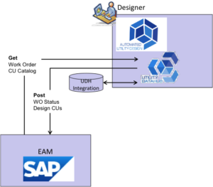
Integration of AUD with SAP/EAM is accomplished via the SBS Utility DataHub™ Design – EAM module (UDH-EAM). UDH-EAM is a configurable interface that supports compatible unit and work order integration with EAM systems, including SAP via services (REST and SOAP) or native vendor specific APIs. The diagram below shows major integration points and data flows between AUD and SAP/EAM.
The UDH–EAM module provides a single point for designers to exchange data with EAM. Utilities that change EAM systems are able to reuse the integration with minimal configuration changes.
How does AUD integrate with EAM, GIS, and Mobile?
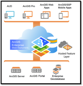
SBS provides both AUD and the Utility DataHub™ (UDH) products. AUD is the design tool, and the UDH suite of integration modules provides the integration. The solution is architected to leverage existing infrastructure, network, and security. Integration is implemented via services (REST and SOAP) or native vendor specific APIs. UDH includes three modules: Design – EAM (UDH-EAM), Design – GIS (UDH-GIS), and Design – Mobile (UDH-Mobile). These modules configure interfaces with SAP/EAM, GIS, and mobile applications respectively. The diagram below shows typical AUD solution architecture components and key data flows.
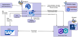
The UDH-GIS module is configured to transform models between the GIS and AUD. The module includes multiple readers and writers to support most commercial GIS systems including Esri ArcGIS, ArcFM, ArcGIS Utility Network, and GE Smallworld. For integration with ArcGIS Utility Network, UDH-GIS leverages ArcGIS feature services for a bi-directional integration. This architecture allows UDH-GIS to share designs with authorized users and other enterprise systems including Esri-compatible mobile systems such as ArcGIS Field Maps or Locusview. The following recording shows how this architecture can be leveraged in the AUD and Esri Field Maps integration: https://www.youtube.com/watch?v=bjWVX70BT6M.
What common integrations exist between AUD and identity management solutions?
Access to AUD is managed through security access to AutoCAD®. Once accessed, the Utility DataHub™ modules control access to external systems and capabilities within AUD through Active Directory groups (security templates). For instance, a user may be granted access to AUD to view the design but may be denied editing privileges, approval status, or access to EAM.
For integrations with Esri ArcGIS services, the solution relies on the ArcGIS Portal to authenticate and authorize the user. IWA, SAML, or token-based protocols are supported at the product level.
How does AUD work with Esri's Utility Network (UN)?
AUD and Esri’s Utility Network (UN) can be integrated via the SBS Utility DataHub™ (UDH) to significantly improve utility workflows. The addition of UN makes geospatial data available to support the design process. AUD in turn keeps the GIS utility network up to date and also allows users to access GIS and AutoCAD software to model and visualize various network layers during the design phase of a project.
Although there are several integration points, the following linkages are particularly important:
· Base geographic data: GIS provides the necessary base map to initiate the design process. The addition of network-based data facilitates the ability to define the work location affected by design and supports creation of the project work area.
· Design-based analysis: During the design process, it may be necessary to support engineering analysis unique to the enhancements being planned for the network. This analysis is typically performed within AUD by accessing GIS network data.
· System-level analysis: An Esri environment with a valid UN for ArcGIS Enterprise becomes a platform that enables AUD to obtain results from system-level analyses needed to support the broader implications of the design improvements.
Those data sources and subsequent analyses deliver critical information to enable an efficient, high-quality design process. The design-specific requirements of the workflow demand a set of data transformation and business processes:
· Augmentation of the GIS data with more-detailed asset information
· Transformation of data from cartographic standards to design and construction standards
· Engineering properties to support calculations
· Network validation
The integration of the GIS and design-data sources provided by Utility Network, AUD, and Utility DataHub™ is a powerful synergy that pays valuable dividends as design solutions are able to leverage GIS network information.
For more detailed information about this topic, please visit: https://spatialbiz.com/utility-distribution-design-and-esris-utility-network/ https://spatialbiz.com/autodesk-esri-sbs-the-partnership-to-know-about
How does the AUD Utility Network integration compare to the SBS Esri Geometric Network offering?
The SBS Utility Network (UN) integration exceeds the current capabilities SBS offers for geometric network integration. The new architecture replaces the original OSGeo Feature Data Option (FDO) integration based on legacy ArcSDE and ArcObjects with a service-based integration that is fully aligned with the ArcGIS Enterprise / Utility Network architecture. This provides a number of benefits:
· AutoCAD-based engineering design is seamlessly integrated with ArcGIS Enterprise and Utility Network using the SBS AUD product.
· AUD designers are Esri Named Users, ensuring the appropriate security protocols are in place.
· Esri data sources are directly available within AUD to support engineering design.
· Esri Utility Network can provide advanced network analysis services (such as network trace) to the designer during an AUD design session.
· Design, engineering, and construction data is published to Esri Field Maps and third-party mobile applications.
A diagram of the integrated architecture is shown below:
Further details can be found in the article on Esri UN integration at the SpatialBiz blog: https://www.spatialbiz.com/utility-distribution-design-and-esris-utility-network/.
What are the capabilities between AUD and Esri versions including ArcGIS Pro and the Utility Network?
AUD is seamlessly integrated with ArcGIS Utility Network using Utility DataHub™ Design – GIS. The solution utilizes ArcGIS API for this bi-directional integration. Therefore, ArcGIS Pro and the ArcGIS Utility Network can be upgraded (i.e., new versions installed) without impacting the integration and AUD. As a member of Esri’s Early Adopter Community program, SBS ensures that our AUD and Utility DataHub products are “Release Ready” for all new data model elements and APIs introduced by Esri.
How are design standards implemented in AUD?
Design standards are implemented in AUD through the blocks, model, and AUD rules engine. Implementing changes to the standards within AUD can be accomplished through the user-friendly SMART tools. Graphic displays of specific standards can be stored in the template and inserted into the document.
How can users leverage previous designs in AUD for new jobs that have similar requirements?
AUD designs are created in a standard AutoCAD® DWG file. All the design data, including a snapshot of referenced data layers, changes to GIS network features, and the design CUs are stored in a single drawing. This allows AUD designers to leverage previous designs for new jobs that have similar requirements. If desired, a previous design DWG file can be copied, altered based on the new job requirements, and linked to a new work order. Utility DataHub™ Design – EAM module can be configured to automate this process.
How is as-built data used to update designs in AUD and then to update EAM with actuals?
SBS has developed integrated solutions via the use of Utility DataHub™ Design – Mobile to support as-built workflows. Please refer to this YouTube video to view a brief demonstration based on ArcGIS Field Maps: https://www.youtube.com/watch?v=bjWVX70BT6M.
What filtering capabilities does the AUD user have inside the tool (i.e. design defaults and searching for material)?
AUD provides a wide variety of filtering capabilities to include setting profiles that when set will remove any material not included in the profile. For example, a service order profile will not include transmission pipes, caps, etc. in the search and selection. During a design, designers will be able to search for specific material utilizing any attribute.
How does AUD handle periodic updates (i.e. partial posting) made to an as-built if the job duration is days, weeks, months, etc.?
AUD can be configured to support various “partial posting” scenarios. The configuration is primarily driven by the business process and status or data conditions that are enforced by other systems participating in the process (such as SAP/EAM, GIS, and Operations).
Option 1: Handle the partial posting at a design work order level when a subset of design features can be tagged in AUD as “ready for posting to GIS” and/or re-assigned to a sub-work order.
Option 2: Enter the entire design in the GIS as “proposed” and then use GIS tools to switch it to “in-service” when a respective notification is received.
Also, the Utility DataHub™ Design – GIS (UDH-GIS) module supports the publishing of the design data from AUD to the design container (in the ArcGIS Enterprise Hosted Feature layers) where the design data can be staged for processing in GIS. This allows granular control of what work locations are to be posted to GIS (i.e. added to the network as “On-Line”) based on periodic status updates from the as-built.
Aside from AUD utilizing current GIS landbase data, can a designer add survey grade data to the design AND pass the updated data to GIS?
Yes, this is a core capability of AUD.
Substation Design Suite™

How do I use SDS with Autodesk Infraworks?
How do I install SDS?
How do I import Autodesk Civil3D data into SDS?
How do I run a 4 Conductor Cable in SDS?
What are the hardware requirements for SDS?
Substation Design Suite™ Physical for Autodesk Inventor requires the same hardware specifications as Autodesk Inventor, which can be found here.
Based on feedback from current clients, SBS highly recommends purchasing this additional hardware:
· A solid-state hard drive
· 32 GB of RAM with the option to expand to 128 GB for larger substations
· Graphics card larger than 4 GB (Refer to Autodesk’s Certified hardware list.)
· 4K monitors (Required to harness the graphics card capability.)
Please note also that performance will be greatly enhanced if working files reside directly on the workstation’s hard drive. Opening files from a network drive can create potential performance issues. A document management system can be set up to pull the file from the network drive for editing then return the file to the network drive once it has been saved.
Substation Design Suite™ Protection & Control for AutoCAD Electrical requires the same hardware specifications as Autodesk AutoCAD Electrical, which can be found here.
Does SBS recommend using sheet sets in Substation Design Suite™?
Whether an organization chooses to use sheet sets depends on the workflow. SBS recommends using sheet sets in major assemblies, major subassemblies, or detailed shop fabrications. Using sheet sets allows users several key advantages:
·View all plans within one sheet set
·Make speed revision changes
·Split up large models to get desired views
·Copy views
·Group drawings together for printing
However, when using AutoCAD Electrical, SBS does not recommend using sheet sets. AcadE’s Project Manager provides many advantages to working in a single file, one of which is the title block update feature. Additionally, using single-sheet drawings in this workflow minimizes hardware requirements and maximizes collaboration by allowing multiple users to access the files.
Does SDS require access to any data hosted in the owning vendor’s site?
Access to data is required only to authenticate licenses. No data is sent to or hosted by SBS.
Does SDS require elevated rights in order to install on workstations?
Yes, administrator rights are required for installation although many organizations deploy installment packages internally.
What is the process to keep SDS updated with the latest new patches and releases?
All updates are posted to portal.spatialbiz.com.
What software security protocol does SBS follow?
All code development (code based) is protected behind “Deny Access” firewalls on AWS. Only authorized SBS personnel are whitelisted through the security group. SDS is an Autodesk plug-in written in .NET code in Visual Studio and Visual Lisp. It is compiled, built, and tested on a Jenkins build server environment and then code signed with a valid SSL certificate.
Does SDS utilize any APIs?
Because SDS serves as a plug-in to Autodesk products, SDS utilizes APIs made available by Autodesk. SDS does not provide customer-facing APIs.
How do I utilize Vault’s “Copy Design” feature with an SDS-P&C (AutoCAD® Electrical) project?
This technique provides similar results as the SDS-P&C “Copy Project” tool but does not require AutoCAD Electrical to complete. To execute this process, you must have access to the Vault, the folders containing the AutoCAD Electrical project (WDP) file, and all related drawing and reference files you wish to copy.
1. In the Vault client application, open the folder of the file you’d like to copy and right-click the AutoCAD Electrical project file (WDP file).
2. Select “Copy Design.”
3. In the copy design dialog, select “All Files.”
4. Right-click over any file and select “Copy To.”
5. In “Select Vault Location,” create a new folder to copy to (if needed).
6. In the numbering panel, right-click in the empty area.
-
- To set permanent values:
- Select “Set Default Prefix and Suffix.”
- Set desired values.
- To set temporary values:
- Select “Set Values.”
- Set desired values.
- To set permanent values:
7. Use “Find and Replace” to correct file names as necessary.
8. Click “Execute Copy.”
9. Close the copy design dialog box.
10. Refresh Vault display.
You now have a new AutoCAD Electrical project that is an exact copy of the original project. The new project is ready for use.
Many customers find the SDS-P&C Data Editor and Swap Block and other project and drawing editing tools to be highly beneficial when utilizing Vault’s “Copy Design” feature to start a new project.
Detailed information on these commands can be found in the SDS-P&C Help Menu. If you need further assistance, please contact us at support@spatialbiz.com.
What are the benefits of using paper space?
Using paper space rather than the model space will:
- Simplify publishing
- Allow scale factors through viewports
- Simplify plotting and changing scale
- Enable modeling of all content 1:1 real size with space and measurement benefits
- Create efficiency gains by simplifying the scaling of objects
- Produce cleaner XREF-ing
- Provide scaling of linetypes
- Enable Sheet Set Manager in Layouts
- Allow multiple layouts and views of the same content
- Enable annotation scaling if desired
What are the benefits of ensuring correct AutoCAD page setup in the main .dwt?
It is extremely important to get the initial page setup right in the main .dwt for plotting and publishing the .dwg files. This is not changeable in bulk later. Proper set up will:
- Maximize efficiency by saving time and clicks and reducing potential errors
- Prevent user frustration
- Facilitate plotting consistencies
- Ensure a consistent end-product to the field
- Prevent large amounts of re-work
How should I run QA and QC?
Using a spreadsheet export is one of the best methods to run QA and QC on AutoCAD Electrical work. Customize the template to include and verify custom attributes as well as SDS attributes. Using a spreadsheet template will:
- Make SDS and custom attributes available for QA and QC reports
- Allow flexibility in brownfield work
- Decrease chances of errors
- Allow for tailoring of what a utility wants to see in order of priority
In your experience, what are the biggest factors affecting the successful implementation of P4A?
There are many factors that affect the outcomes of a technology implementation. One of the most important things is to recognize that this is a transformation for your organization. We highly encourage you to communicate frequently with all the stakeholders within your organization about the status of the implementation and the benefits to be derived from the technology.
- Level of commitment from customer – we would prefer you to defer rather than dabble.
- 3D Content – developing / acquiring 3D content is a part of the process
- Quality of your existing data – your data feeds the intelligence in P4A that drives the outcomes you desire.
- Steadfastness of your procurement processes – how you order things and will order things in the future drives many decisions when configuring P4A.
- Decision-making process – this may be the most crucial factor; you must establish an optimal process for decision making and authorize people to act.
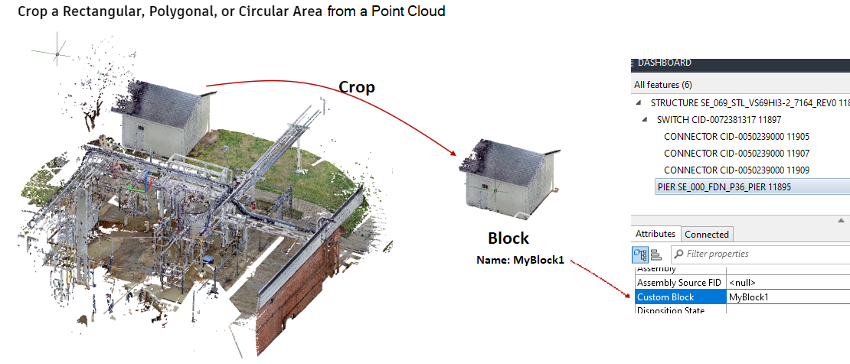
How to import point clouds/scans/print?
Point clouds are supported through the Map3D (Autodesk) interfaces, so searching for Map3D and point clouds will give you a lot of ideas on capabilities:
To Bring In Point Cloud Data (Map3D) – Autodesk Knowledge Base
In P4A, there is an additional ability to set a Feature’s representation (we call it ‘Symbology’) to any AutoCAD block using the “Custom Block” attribute. This presents an interesting workflow in that a Point Cloud can be cropped (Knowledge base article), then Blocked (BLOCK command), then set to be used as the Symbology for that Feature. There is a drawback in that it will not have Ports and use the “auto-connect/auto-orient” functionality that is typical P4A, but it gives Designers a way to use Point Cloud representations of out-of-date or one-off Equipment.
How to put the P4A 3D model on to 2D plan sheets (process)?
During the design process, P4A acts as an assistant by creating and maintaining Features, Attributes, Connectivity, Material Lists, Validations, etc. But when the design is complete and ready to be published, P4A leverages core AutoCAD functionality. P4A was designed so that all the standard AutoCAD plot generation components your users are familiar with remain an integral part of the publishing process.
So, process-wise you are looking at using AutoCAD clipping commands (e.g., XCLIP) and viewports (top, front/side, etc.) to generate plots/sheets/etc. P4A enhances this process with commands, such as, AUDTABLE (auto-generated tables based on the intelligence in the design) and AUDCALLOUT (for assistance in placing material item tags) but behind the scenes most of the positioning and viewing is achieved via standard AutoCAD plot generation.
How to update EG survey surface if there is a change (process)?
Any AutoCAD Map3D recognized civil surface may be used. Once it is imported or referenced into the current drawing, there is a command available called AUDELEVATIONSET. This command allows for setting active civil surfaces, controlling how P4A inherits and sets elevation from those surfaces and/or resetting items to a new surface.
Process-wise, that means Surface A is being used, set as active. Any P4A Feature placed inherits from that Surface. Surface B comes along later, Designer would set that surface to Active, set the original surface to Inactive and click “Set Elevation” for a selected group of Features. They would reset to the new surface elevations. Depending on configuration, you may also need to click the “Update Model” button to Refresh the Wire/Bus geometries after the structures move (to recalculate based on the new heights).
Will we be able to convert existing Inventor models to P4A and would we get the same metadata?
Yes. There will likely be some review and (slight) modifications to take advantage of ports in P4A. The Inex tool is meant to provide a way to create P4A-ready models in Inventor and transition them over to P4A “parts”.
Yes, configured correctly, you will pass your Inventor metadata to P4A. There is a mechanism available in P4A allowing an attribute named the same in both applications will auto-populate the attribute on import.
Is file storage an issue? Do we need to use Autodesk Vault?
P4A does not require Vault to function properly. The choice to implement Vault as a part of your overall engineering design system is a function of the size of your organization and the complexity of your workflow. SBS advises customers to contact a utility-workflow focused Vault reseller to discuss the pros and cons of implementing Vault for your scenario.
Vault and P4A have different intended functionality. Vault is valuable from an archiving and retention standpoint, whereas P4A facilitates design drawings. P4A is not a document management application like Vault.
All Autodesk products have a plug-in for Vault that allows for searching, history, revision control, etc. Many manual tasks are automated or streamlined using Vault and the Vault plug-ins. Vault inherently supports Revisions (versioning) so that past versions of drawings can be supported, regardless of naming conventions, e.g., a typical file management workflow might be “Drawing_Rev0” becomes “Drawing_Rev1”, whereas Vault allows for file name “Drawing 1” to remain constant while maintaining an archive of each revision.
How does the technical support work? Is there an hourly rate? Does any support come with the software?
All purchases of the Substation Design Suite are covered by the SBS End User Licenses Agreement (EULA) and the support terms and conditions for the product purchased. SBS maintains a support site ticketing system where users can submit tickets for SBS to investigate. SBS advises all customers to complete product training upon purchase and to contract with SBS for start-up assistance. SBS typically works closely with customers to determine the post-training support that is the best fit for that customer.
Do you recommend Inventor for the library development?
Many users find Inventor to be convenient for creating 3D content, however, Inventor is not required for the creation of P4A 3D content. P4A only requires a 3D DWG block. The native source of the block is not a consideration for P4A. SBS advises customers to utilize applications that their staff is most familiar with already for the creation of 3D content. Further, SBS advises customers to first utilize the content sources available to them, OEMs (Original Equipment Manufacturers) and Utility Content, prior to developing content from scratch.
Are you able to provide a list of the standard models so we can see what we would need to add to it?
- GE Circuit Breakers (all voltages 72.5kV and up)
- EMA 38kV Circuit Breakers
- Vertical Breaker Disconnect Switches
- Arresters
SBS provides its customers with access to our Utility Content site to facilitate the development of a customer-specific 3D content library. The content SBS makes available, either in the OOTB configuration or via the utility content site, is provided for customer convenience and should be vetted by the customer for accuracy prior to incorporating into a production model (real-world design). SBS has partnered with several original equipment manufacturers (OEM) who are making their 3D models available for download. SBS advises customers to establish a workflow with its major equipment manufactures that results in the OEM providing 3D model content directly to the customer as part of its purchasing and approval process. SBS advises, prior to establishing a 3D model submittal expectation with the OEM, customers to become familiar with the modeling strategies and best practice guidelines provided on our Knowledge Base site. In general, the substation design does not require the same level of detail the OEM requires to manufacture the equipment.
Does SDS Physical for Inventor provide grounding calculations?
Substation Design Suite™ (SDS) Physical for Inventor does not provide grounding calculations. However, it can import the results of a design completed by qualified engineers utilizing existing ground grid analysis software such as CDEGS, WinIGS, ETAP, etc.
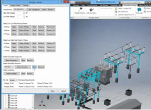
What type of design checks does SDS Physical Inventor perform?
Substation Design Suite™ (SDS) Physical for Inventor provides the following design checks:
·Check Parts by Phase
· Grounded Equipment
· Grounded Structure
· Insulator Check
· Basic Insulation Level (BIL)
· Phase to Ground
· Phase to Phase
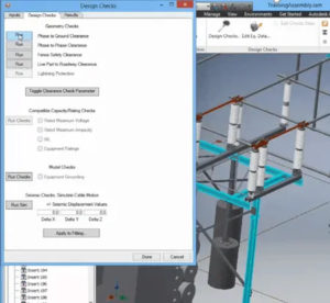
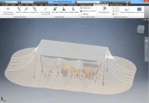
What type of lightning protection does SDS Physical for Inventor provide?
Substation Design Suite™ (SDS) Physical for Inventor provides rolling sphere and cone protection analysis based on IEEE standards.
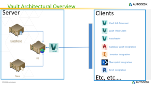
How are Vault Data Server (ADMS) and Vault File Server (AVFS) arranged for SDS Physical for Inventor?
Vault Data Server
3D substation design projects contain both models and drawings and will naturally vary in size based on project complexities and customer requirements. Depending on the modeling strategies utilized, both large substation projects and small substations could easily generate 500MB of data. In 3D substation design, a single model can be utilized many times and only have a single instance of the file. One substation design could have more than 4,000 individual files.
As a result, Substation Design Suite™ Physical for Inventor relies heavily on Autodesk Vault Data Server. The Vault Data Server should be located on a dedicated computer. Spatial Business Systems (SBS) recommends a 500GB solid-state drive (SDD) and 32 GB of RAM for the primary drive where the Vault Data Server is installed since the server itself is managing the data links and workflow.
Vault File Server
As the model and drawing data increase, organizations can accommodate the increased storage demand by expanding Vault File Server. Subsequent drives can be added to the Vault File Server and each can contain segmented Vaults. SBS recommends configuring a “Training Vault” environment in addition to the Production Environment Vault to facilitate testing of workflows and methods. Since the file size of a substation design project may reach 1 GB or more, SBS recommends using at minimum a 500 GB SSD and 32 GB of RAM for each additional drive.
Hardware requirements for the Vault Data Server and Vault File Server can be found here: https://knowledge.autodesk.com/support/vault-products/learn-explore/caas/sfdcarticles/sfdcarticles/System-requirements-for-Autodesk-Vault-2020-products.html
Server Access
Users can experience latency and similar performance issues stemming from multiple users accessing a single server simultaneously. Users should have access to the server with little interruption, meaning network hubs and switches should be minimized between the user’s computer and the vault servers.
Server Backup
Vault does have a backup utility of its own, but it tends to become more unreliable as the file stores approach 1TB or more. To mitigate backup and recovery concerns, SBS recommends that organizations with large data stores utilize SQL backup utilities.
What is Vault Data Standard (VDS), and how should it be configured to work with Substation Design Suite™ Physical for Inventor?
Autodesk offers its clients Vault Data Standard (VDS), a free data control feature that allows for automatically populating the metadata required for drawings, assemblies, and parts for both Autodesk Inventor and AutoCAD Electrical.
When using Substation Design Suite™ Physical for Inventor tools to create part (.ipt) models on the fly, SDS creates the filenames, part numbers, and iProperties. VDS should be configured to not affect these parts; otherwise, VDS will interrupt the SDS creation of the parts and will cause an error.
VDS commonly interferes with the following items:
·Flex Conduit and Straight Conduit
·Cable
·Bus and Bent Bus
·Ground Leads
To prevent interference with Inventor parts (.ipt) and SDS created parts, SBS recommends either turning off VDS or simplifying VDS. When VDS ignores these parts, users can enter the metadata manually. This is often of little concern because Library parts (.ipt) are most often used in substation modeling. With Inventor drawings and assemblies (.iam), use VDS as desired.
Does SDS require any firewalls to be opened?
It may be necessary to whitelist portal.spatialbiz.com and/or support.spatialbiz.com. Both URLs point to the same server.
What software security assurance does SBS provide to validate that SDS is free of security vulnerabilities?
SDS functions as a plug-in to Autodesk software and does not collect or transmit customer data back to SBS other than license user credentials.
Does SDS collect or send any data to the software provider or any other third-party vendors?
SDS collects license authentication information. Only user credentials are maintained by SBS.
What connection type and encryption does SDS use between the app or plug-in and the owning vendor?
Connection to licensing servers is encrypted through port 443. Per the SSL certificate for portal.spatialbiz.com and support.spatialbiz.com, encryption for the connection is TLS_ECDHE_RSA_WITH_AES_256_GCM_SHA384, 256 bit keys, TLS 1.2.
How do I know if I should use SDS Physical for AutoCAD or SDS Physical for Inventor?
Each application is better suited for different needs. View our comparison page to see which one would be better for you.
How do I set up drawings?
Set up WD drawings in portrait style in model space then rotate them in a viewport. This will:
- Improve ergonomics by avoiding looking at drawings sideways
- Save time and clicks
- Reduce potential for errors
- Allow for needed scaling to reduce from 1:1 in model space to the needed paper scale
- Look more realistic and similar to the panel being wired
How many .wdt files should I use?
Using only one or two .wdt files will create less chaos in the long-term when updates need to be made. Centralizing the .wdt file will:
- Prevent discrepancies and errors from multiple files across different projects
- Decrease time and frustration with having to update multiple files in all project folders when changes are made
How should I organize my files for reporting?
SBS highly recommends creating standard .set files for reporting. Creating standard .set files will:
- Improve efficiency by reducing time and clicks spent on non-meaningful work
- Ensure consistency and enforce standardization in project report creations by different users
- Enable the AutoCAD Electrical Automatic Reports functionality
SBS also highly recommends setting up a custom default.wda file. Without a default.wda file, utility custom attributes will be unavailable for reports. Creating a default .wda file will:
- Make custom utility and SDS attributes available for quality assurance (QA) and quality control (QC) reports and/or project transmittal reports
- Prevent users from having to create their own project-specific files
- Allow files to be used in brownfield work
What attributes do I give symbols?
Give all symbols multiple WD_WEBLINK attributes. Doing so will:
- Help enable end goals for multiple linked documents being accessible through AutoCAD Electrical
- Automate inserting additional hyperlinks into the surfer at a later date
- Save time by adding attributes to all symbols now and having them ready for future use
Considering the advantages of SDS P4A, are there still additional benefits to utilizing Vault Professional?
Yes. Vault and P4A (Physical for AutoCAD) have different intended functionality. Vault is valuable from an archiving and retention standpoint, whereas P4A facilitates design drawings. P4A is not a document management application like Vault.
All Autodesk products have a plug-in for Vault that allows for searching, history, revision control, etc. Many manual tasks are automated or streamlined using Vault and the Vault plug-ins. Vault inherently supports Revisions (Versioning) so that past versions of drawings can be supported, regardless of naming conventions, e.g., a typical file management workflow might be “Drawing_Rev0” becomes “Drawing_Rev1”, whereas Vault allows for file name “Drawing 1” to remain constant while maintaining an archive of each revision.
I am interested as to what the time, cost, and process to implement P4A will look like.
Of course, each implementation engagement is unique so it is difficult to address this question specifically, however, our process is focused on building up your core understanding of what drives intelligent operations within P4A and equipping your people with the skills to self-manage and expand the configuration.
P4A is provided out-of-the-box (OOTB) with a robust substation industry model configured to support industry standard design and material practices. It is expected that you will want to adjust the configuration to satisfy your specific requirements. SBS has developed the P4A product to facilitate user modifications to the OOTB configuration.
Our intent is to reach a suitable point where your people are novice users and maintainers of the P4A system within 6 months. Your team will grow to expert users and maintainers only over time by using the product in daily production. As with any major investment, you should expect to perform routine maintenance, aka continuous improvement, on your P4A system so that the system continuously matches your most current design and material standards.
In P4A, can prefix letter be automatically added in front of BOM (Bill of Material) IDs?
Yes. Item Numbers/BOM Numbers are set as an attribute during placement and can inherit any type of naming schemes via rules or preset attributes.
In P4A, can bolt/hardware size & length be automatically added to BOM based on size of hole and thickness of material its penetrating plus 1”?
Remember, P4A is highly configurable and can be adjusted to meet your requirements. Out-of-the-box, P4A is provided with bolt-hole sizing rules that can use a top and bottom mounting standard to validate bolt hole sizes, hole spacing, etc. to ensure a proper match between two mating surfaces.
What computer requirements are needed to run the software?
Many factors, such as hardware capability, hardware settings, Windows settings, AutoCAD settings, and modelling techniques affect the performance of SDS-P4A. For our latest guidance on how to optimize performance of P4A (Physical for AutoCAD), please refer to our knowledge base article titled “SDS-P4A Graphics Performance”.
What comes with the “out of the box” P4A package?
To run SDS-P4A, you will need to have AutoCAD and AutoCAD Map3D installed. SBS (Spatial Business Systems) recommends installing the most current version of the AutoCAD applications to take advantage of the latest graphic handling features provided by Autodesk. Once you have installed the P4A plug-in to Map3D, you will install the P4A out-of-the-box (OOTB) configuration. The OOTB P4A configuration contains industry standard data-models and the associated graphical representation of these data models. The OOTB configuration is configured to help users complete exercises provided during training. The OOTB P4A configuration has been structured to facilitate the customer’s modification to represent their specific model data and graphical representations, as well as modification to the two OOTB outputs (reports and drawings) generated by P4A to meet the customer’s specific output requirements.
Are there network license options or are they assigned to specific computers?
All Substation Design Suite products are sold as named-user licenses on an annual subscription basis. Each user within your organization will need login credentials to the SBS support site. On the SBS support site, your license administrator will assign a specific SBS license to a specific user.
Utility DataHub™
What interface capabilities are supported via UDH?
Utility Data Hub™ (UDH) has five modules:
· UDH Design – EAM
· UDH Design – GIS
· UDH Design – Mobile
· UDH Analysis
· UDH Substation
Visit the Utility DataHub™ webpage to learn more about these modules.
Is UDH required to use AUD?
Utility DataHub™ (UDH) is commonly used to connect designs to enterprise asset management (EAM), work order systems, Geographic Information Systems (GIS), engineering analysis programs, and mobile devices. However, UDH is not required to perform the designs or to create an automated bill of material.
Licensing

What types of licenses does SBS provide?
SBS license types vary based on the product being purchased.
- The end-user licenses for our intelligent design solutions, AUD and SDS, are named user licenses. Please note: Any previously purchased single-use or multi-use licenses will continue to work. However, the user will have to create and sign into their SBS support profile to retrieve the product license. If an organization has previously purchased multi-user licenses and wishes to purchase more, they will be named user licenses.
- Utility DataHub is available via perpetual license, sold by environment.
- Our FME plug-in products typically follow the licensing models of Safe Software’s FME product.
Can I get a trial license of SBS software?
SBS offers trial licenses of Substation Design Suite™ (SDS) with the purchase of SDS Physical and/or SDS Protection & Control Training. Licenses are active through the duration of the training course.
SBS training course options can be found here.
What Autodesk versions do SBS products support?
SBS products such as Automated Utility Design™ and Substation Design Suite™ support the current version as well as the previous three versions of Autodesk’s AutoCAD and Autodesk Inventor. While projects may run on earlier versions, they will not be supported by SBS.
Does SBS offer volume discounts on software licenses?
SBS offers multi-year purchase discounts but no volume discounts.
Training

What training and support does SBS provide for AUD users?
SBS training is done throughout the semi-agile implementation process. SBS typically trains the project leaders and subject matter experts early in the implementation cycle to support the discovery process.
We offer two primary AUD courses: AUD User Training and AUD Configuration Training.
AUD User Training
AUD User Training is a two-day, instructor led course. This training is intended for day-to-day users of AUD as well as project leaders, subject matter experts, and design leaders that need to understand the user functions of AUD. Training is performed utilizing the AUD out-of-the-box configuration. Training includes lectures, hands-on AUD exercises, and the following lesson modules:
- Lesson 1: AUD Concepts
- Lesson 2: Data Import
- Lesson 3: Analysis Basics
- Lesson 4: Material Ordering Basics
- Lesson 5: Layout Tips and Tricks
- Lesson 6: Advanced Overhead
- Lesson 7: Advanced Electric Layout
- Lesson 8: Resolving Analysis Issues
- Lesson 9: Editing the Material Order
- Lesson 10: Creating Staking Sheets
AUD Configuration Training
AUD Configuration Training is a two-day, instructor led course based on the out-of-the-box AUD product. Training includes lectures, hands-on exercises, and the following lesson modules:
- Lesson 1: AUD Configuration Overview
- Lesson 2: Configuring Domains
- Lesson 3: Configuring Industry Models
- Lesson 4: Configuring the Material Catalog
- Lesson 5: Configuring Custom Attributes
- Lesson 6: Introduction to Configuring Rules
- Lesson 7: Configuring the Details Library
In addition, SBS provides an eLearning environment to deliver application-specific training for AUD. Updates to eLearning that address new release capabilities are provided on a subscription basis. eLearning can be enhanced with content that is unique to client business requirements, allowing users to receive training as well as tips and tricks to address design practices within their own work environment. Common “how to” questions are also addressed via the AUD Peer Utility Group (PUG) user community of individuals from AUD user companies. PUG membership is available at no cost.
What training is available for Substation Design Suite™?
SBS offers two specialized courses that focus on the configuration and use of the Substation Design Suite™ (SDS) products. Our instructor-led courses provide the most up-to-date information on SDS design and software training in a series of twelve to sixteen sessions. Both courses are available online via web meetings in two-hour increments. Onsite training sessions are currently unavailable due to COVID-19.
SBS also offers mentoring programs that provide practical guidance in the use of the SDS product offerings.
To see prices and more extensive details for each course as well as information about our mentoring programs, click here.
What do I need to do in order to prepare my organization for SBS training?
Please prepare your organization for full attendance at each training session with proper hardware and software already installed. Being fully prepared for SBS training will optimize your organization’s time spent in training by keeping technical issues and distractions to a minimum.
Hardware
Please review the hardware requirements of the software for which you are receiving the training. If your current hardware does not comply with minimum requirements, procure and set up the hardware before scheduling the training. SBS software requirements are listed below:

Automated Utility Design™ requires the same hardware specifications as Autodesk’s AutoCAD, which can be found here.

Substation Design Suite™ (SDS) Physical for Autodesk Inventor requires the same hardware specifications as Autodesk Inventor, which can be found here.
Substation Design Suite™ Protection & Control (SDS P&C) for AutoCAD Electrical requires the same hardware specifications as Autodesk’s AutoCAD Electrical, which can be found here.
Software
Whether you are purchasing SBS software or using SDS trial licenses for your training, please ensure that the software is installed and operational at least one week before your scheduled training. Installation instructions can be found on the SBS Support Portal.
Attendance
It is imperative that attendees be fully present and free of distractions for the entire duration of the scheduled training. Missing even twenty minutes of training can set a student back or derail the lesson schedule.
SBS training course options can be found here.
Getting Started

How do I obtain 3D content to build my intelligent substation models?
Prior to embarking on creating content, SBS encourages organizations to investigate sources for substation content that may already be available to them:
·SBS portal at https://www.utilitycontent.com/
·Original Equipment Manufacturers (OEM)
·Investor-Owned Utilities (IOU) organizations, many of whom have already initiated 3D modeling practices within their organizations
·The SDS Industry Consortium (SDSIC) NAUCSI initiative, which is a content sharing initiative among mid-sized and larger investor-owned utilities at https://sdsconsortium.com/
Although some projects will necessitate custom content, the vast majority of 3D models required for substation design should be viewed through the lens of “Level of Development” rather than “Level of Detail.” Adopting the “Level of Development” mindset empowers engineers and designers to focus on conveying design intent to all stakeholders rather than on developing pretty pictures. The most advanced and efficient users of 3D technology balance visual-fidelity and critical information-exchange. A moderate visual-fidelity model supported with comprehensive meta-data will, in most cases, deliver on the promises of BIM (Building Information Model) design while reducing the labor investment required to support higher-precision unique models.
What software do I need to get started with intelligent substation design?
Autodesk Inventor Professional is required to run the Substation Design Suite™ (SDS) Physical product. Autodesk’s AutoCAD Electrical is required to run the SDS Protection & Control (SDS P&C) software modules.
SDS Physical and SDS P&C are purchased separately from SBS. Autodesk products can be purchased directly from Autodesk or through an authorized Autodesk reseller.
What hardware do I need to get started with intelligent substation design?
Automated Utility Design™ requires the same hardware specifications as Autodesk’s AutoCAD, which can be found here.
Substation Design Suite™ (SDS) Physical for Autodesk Inventor requires the same hardware specifications as Autodesk Inventor, which can be found here.
Substation Design Suite™ Protection & Control (SDS P&C) for AutoCAD Electrical requires the same hardware specifications as Autodesk’s AutoCAD Electrical, which can be found here.
What is the implementation process for AUD, and how does SBS support this implementation?
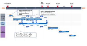
SBS utilizes a proven, semi-agile process for implementing our software products. The process involves agreement upon a general set of business and functional requirements as well as a technical implementation plan. However, as the system is highly flexible, and no two designs are the same, SBS understands that adjustments to the acceptance criteria and definitions of implementation requirements may change as knowledge transfers between SBS and our client. The semi-agile approach minimizes the time in requirement meetings and increases early access to the system by end users to evaluate the configuration. By using a semi-agile approach, small changes can occur in each iteration, thus minimizing the impact at testing and roll-out. The final deliveries more closely address user requirements, ensuring successful adoption and reduced change management.
A high-level view of a standard AUD implementation integrated with GIS and SAP is shown below. The SBS schedule adapts to each utility’s unique testing and acceptance criteria.
What options does SBS offer to implement intelligent substation design at my utility?
Here is a preliminary list of items to consider when getting started with Substation Design Suite™:
- Acquire the suggested hardware. Inadequate hardware negates the benefits of SBS solutions simply because of performance issues.
- Schedule the recommended training. SBS team members are experts at the software and its use in your environment, and many SBS trainers have prior experience with the challenges of creating substation designs.
- Structure a project for your staff to work on immediately following the training. SBS encourages a pilot project approach with a team dedicated to implementing and testing the applications within your environment.
Typical Quick Start Engagement for a
Professional Services Firm

SBS team members are available via regularly scheduled sessions to consult with professional service firm users, managers, and IT staff. Consultation topics typically cover:
· Vault configuration, folder structures, and file naming schemes
· IT related topics, shared drives, and hardware
· 3D content strategy, Utility Content, and OEM content
· 2D symbol strategy, UPCS, and standard schemes
· Model development strategy and level of detail
· User consistency and data standards
· Executive management, vision, objectives, and implementation
· Brownfield workflows and Scan‐to‐BIM
Determining which product best serves your organization and your clients is critical in transitioning to new productivity-enhancing technology. Please check out the SBS eBook “Which Product is Right for Me” and schedule a call with the SBS team to talk through details.
Managing data is another essential part of any technology adoption process . SBS will guide your organization to solutions and processes that best serve your needs and the needs of your clients.
In the substation design industry, acquiring content is also a primary point of concern. The SBS team is well equipped to assist your organization in developing a content strategy. Please refer to some of our most popular guidance documents on developing content:
· Addressing the Content Dilemma
· Guide to Acquiring OEM 3D Models
· Transitioning to 3D FAQ
Contact SBS for a more in-depth conversation about implementing SDS.
Is a Document Management System required for intelligent substation design?
A document management system is not required for a substation pilot project or for the creation of a basic design, but it is necessary for a production-level implementation of the Substation Design Suite™ software. The document management system needs to track revisions in construction prints, parts, and assemblies.
Many utilities already have company document management systems that may be developed internally, and others use industry-specific products such as Meridian. SBS recommends Autodesk Vault since it fully integrates with the Autodesk products used for substation design tools and holds legacy files of other design platforms. Many utilities use Autodesk Vault to manage the models and construction documents then have a PDF generator post the documentation to Meridian when projects are as-built and checked back in.
SBS can recommend Autodesk resellers that provide Autodesk Vault implementations. Or utilities can use their reseller of choice, and SBS can oversee the implementation.
What are the benefits of transitioning to 3D modeling and BIM solutions for substation design?
There are numerous benefits from adopting a BIM approach. These can range from better visualization of the installation including virtual walk-throughs to animated construction sequences tied to your project schedule. However, the most immediate positive impact firms typically realize when adopting a comprehensive project modeling approach is a reduction in the number of field fit-up errors and a reduction in incorrectly specified materials. The Substation Design Suite™ products leverage the core capabilities of the Autodesk products your team is already familiar with to provide substation design specific functions that increase your design efficiency and quality.
What is the integration process for your software product, and how does SBS support this integration?
The SBS integration process begins in the early stages of the SBS semi-agile delivery process. The SBS team conducts collaborative working sessions and demonstration exchanges with the client team business representatives and IT staff to understand the existing architecture and workflows. The objective is to determine and agree on how the solution is able to most efficiently plug-in with the existing infrastructure. Through this series of workshops, the teams are able to gain an understanding of the available data sources and accessibility options (e.g. web services, middleware, databases, direct connections, etc.) along with security requirements that must be adhered to for the build out of the integrations. Upon common agreement of architecture and design specifications, the SBS team begins to work with the client team, as well as GIS and EAM subject matter expert representatives, to develop the integration components to adequately validate data exchanges between each system. This follows an iterative process of validation and refinement as more data becomes available to move back and forth between the solution and each integrated component.