Author: SBS

  • Building the Future of Substation Design with BIM

    Building the Future of Substation Design with BIM

    By Al Eliasen, CEO, SBS

    Across the utility industry, BIM has become the standard for large, complex projects. Civil, structural, and architectural teams have already made the shift. Substations, however, have lagged behind. Engineers are still forced to work across multiple tools, creating duplicate documentation, and reconciling data by hand. This siloed work leads to project delays and cost overruns, and delays in one project cascade through an entire project pipeline.

    That is changing. At SBS, we believe the time has come for substations to have a true BIM-native design environment, one that meets the needs of physical and protection & controls (P&C) engineers while connecting seamlessly with the rest of the project.

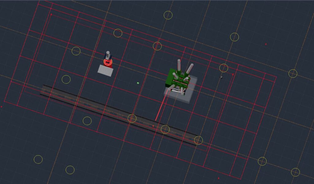
    That is why we are building BIM Substation Designer, a Revit-based platform created specifically for substations.

    The industry is ready for BIM in substations

    Utilities and engineering firms are under enormous pressure: aging infrastructure, electrification, renewable integration, and resource constraints. Projects are bigger, timelines are tighter, and experienced staff are harder to replace. At the same time, BIM adoption is accelerating across every discipline.

    Bringing substation design into Revit is no longer optional, it is essential to meet modern design demands. By unifying physical and P&C design within a single model, BIM Substation Designer removes the translation steps that cause errors, delays, and additional cost. This single source of truth for substation design means design workflows in BIM Substation Designer will have faster QA/QC cycles, fewer design changes, and more accurate construction documentation.

    A BIM foundation creates lasting value

    BIM is more than a 3D model. It is a foundation for data that can support the entire lifecycle of a substation, from design and construction through operations and maintenance.

    BIM Substation Designer extends Revit with the elements that matter most to substation teams: lightning protection, ground grids, bus and cable design, and electrical connections. And because it is part of the same BIM environment as other aspects of a project, all features can be coordinated and delivered consistently.

    For example, a data center project that has the site development plan, building architecture, MEP, and structure models in BIM will now include the detailed substation in the same model, enabling more efficient coordination across the project. Looking ahead, these models can also feed digital twins, GIS integration, and asset management systems, creating long-term value beyond construction.

    SBS brings decades of experience to this moment

    We know this transition will not happen overnight. Successful BIM adoption depends on standards, training, and support, not just software. That is where SBS stands apart.

    Since 2002, SBS has focused almost exclusively on intelligent design solutions for utilities.  Our team averages more than 20 years of utility design experience, and our solutions are in use at hundreds of utilities and dozens of engineering firms worldwide.

    We have earned trust as a strategic partner to Autodesk and Esri, and we have guided utilities through major digital transformations in distribution and substation design. By adding BIM Substation Designer to our current industry leading Substation Design Suite (SDS) platform, we are combining our expertise with a commitment to helping firms adopt BIM workflows with confidence through standards templates, automation, and a community of early adopters.

    A collaborative launch starts now

    BIM Substation Designer is currently in closed beta with select utilities and engineering firms, who are helping shape the product and validate its workflows. We expect to launch commercially in Q1 2026.

    This is not just another software release. It is a foundation for the next generation of substation design. And like every meaningful change in our industry, it will take collaboration, persistence, and shared vision to get there.

    We are ready and excited for you to join us.

    Learn more about BIM Substation Designer and stay in touch with the latest news.


  • Standardizing Utility Design at Scale: PG&E’s Move to Automated Utility Design

    Standardizing Utility Design at Scale: PG&E’s Move to Automated Utility Design

    T&D World recently hosted a webinar, Undergrounding at Scale: PG&E’s Innovations and Lessons Learned, exploring how Pacific Gas and Electric (PG&E) is advancing its ambitious undergrounding program. The session featured insights from PG&E leaders on strategy, technology, and lessons learned from deploying new approaches in the field. One highlight came from Trevor Fulks, Senior Manager of Strategy, Innovation, and Partnership at PG&E, who discussed how Automated Utility Design (AUD) is transforming the company’s design and construction process.

    When large-scale utility projects shift in the field, the ability to pivot quickly can make or break schedules and budgets. For PG&E, the traditional process of redesigning jobs, whether for a small adjustment or a major re-route, was too dependent on individual expertise.

    The readiness to pivot can’t be dependent upon a single person who happens to know their business really well. It needs to be a process feature, an integral part of our process,” Fulks explained.

    That need for agility is a driving force behind PG&E’s rollout of Automated Utility Design (AUD), a tool that integrates engineering rules, design standards, and materials pricing directly into the design process. According to Fulks, AUD is now about one-third deployed across the organization and on a “hockey stick ramp” of training and adoption.

    From Manual Prints to Automated Standards

    Traditionally, construction crews depended heavily on the skills and style of individual designers. Some prints were works of clarity, while others required frustrating levels of interpretation in the field.

    When it’s a very human process to make the design, it is a very human result. Some are great. Some not so great. What Automated Utility Design allowed us to do is standardize that output…best practices become the standard. And that is the only thing you produce, best practice design-wise.” Fulks explained.

    AUD reduces redesign cycle times by embedding calculations and validation checks into the workflow. The program flags issues such as transformer placement or voltage drop before a design reaches the field. It also generates accurate bills of materials on the fly, so estimates stay consistent and reliable.

    Impact on Construction Efficiency

    For those in the field, the benefits are clear.

    When you get the Van Gogh of prints every time, that is going to have a program-level impact on the efficiency of your construction,” Fulks emphasized.

    The efficiency gains are real: faster redesigns, fewer errors, and consistent outputs that help construction crews work more efficiently under challenging conditions.

    Looking Ahead

    With AUD becoming a core part of PG&E’s process, the utility is building not just for today’s projects but for a future where agility, consistency, and efficiency will be critical to meeting California’s energy needs.

    Best practices become the standard.

    That is a simple phrase, but one that captures the transformative promise of AUD at PG&E.


    💡 You can watch the full discussion, Undergrounding at Scale: PG&E’s Innovations and Lessons Learned, on T&D World’s website

  • How Multi-Client Configuration Templates in AUD Help AEC Firms Work Smarter

    How Multi-Client Configuration Templates in AUD Help AEC Firms Work Smarter

    Embedding client standards into AUD templates creates consistency, reduces rework, and helps AEC firms scale efficiently

    For many AEC firms, every new client engagement comes with a fresh set of design standards, CAD requirements, and review processes. These standards are essential for ensuring deliverables meet the client’s expectations, but they also create challenges. New designers and senior designers often need weeks or even months to adapt to a client’s way of working.  Senior staff, meanwhile, spend much of their time interpreting standards, checking work for compliance, and guiding less-experienced colleagues through the details.

    When projects are spread across multiple clients, the complexity multiplies. Switching from one client’s standards to another’s is a fertile ground for errors, and the resulting rework can quietly erode margins and delivery schedules. For distributed teams working across regions, maintaining consistency can be even harder.

    One practical way to address these challenges is by using configuration templates in Automated Utility Design (AUD). This approach encapsulates client-specific rules, CAD standards, and validation requirements directly into the design environment. When applied systematically, this capability can improve the way an AEC firm manages its workload, develops talent, and delivers work across multiple client portfolios.

    Capturing client standards once and using them many times

    In AUD, a configuration template acts as a blueprint for how designs should be created for a particular client. It can include CAD symbology, standard components, validation rules, and other parameters that define “what right looks like.” Once built, it becomes a ready-to-use environment that validates each project step without requiring designers to memorize or manually check every standard. This framework creates freedom for designers to work on the critical engineering design tasks in the workflow rather than thinking about the right color on lines and callouts.

    This approach changes the onboarding process for new team members. Instead of spending months learning the low-level details of a client’s requirements, they can start contributing almost immediately. The embedded validation rules catch deviations automatically, so new hires can focus on the design itself rather than on remembering formatting or drafting conventions.

    Reducing rework through built-in validation

    Rework is one of the quietest but most persistent drains on profitability. A single oversight, such as using the wrong symbol, dimension, or component, can trigger an entire review cycle, delaying delivery and adding unplanned labor hours.

    With client-specific validation rules in place, these issues are flagged during the design process, not after the fact. Designers get immediate feedback when something does not align with the template, allowing corrections to be made in minutes instead of days – dramatically improving the speed to scale. For firms juggling several client projects at once, this proactive error prevention can make a measurable difference in throughput and client satisfaction.

    Changing the role of senior resources

    In many AEC firms, senior engineers spend a significant portion of their time doing quality control. While this ensures deliverables meet the standard, it also limits the number of projects they can influence directly.

    Configuration templates redistribute that workload. Because the templates enforce low-level compliance, senior staff can focus their reviews on the elements that require professional judgment, such as complex design decisions, coordination between disciplines, and creative problem solving. The result is a higher-value use of their expertise and an opportunity to mentor junior staff on the most meaningful aspects of the work.

    Supporting distributed collaboration

    AEC firms increasingly operate across multiple offices and time zones, often with teams spread across different regions or even countries. This can complicate coordination, especially when it comes to ensuring that everyone is following the same client standards.

    A configuration template eliminates the ambiguity. Whether a designer is in the head office or working remotely halfway around the world, they are working in the same environment, with the same rules and tools applied consistently. That consistency reduces friction during cross-regional reviews and makes it easier to move work between teams without losing time to reorientation.

    From process improvement to business advantage

    While the immediate benefit of configuration templates is operational, such as fewer errors, faster onboarding, and smoother reviews, the longer-term impact is strategic. AEC firms that can confidently take on projects for multiple clients without adding overhead are better positioned to scale. They can expand into new markets, bid on a wider range of work, and deliver consistently, even with a dynamic workforce.

    Why this matters now

    The value of configuration templates becomes even clearer when viewed against current industry pressures. The demand for new infrastructure, driven by urban growth, renewable energy projects, and utility modernization, is rising steadily. At the same time, many firms face a shortage of experienced talent as senior engineers retire and younger professionals enter the workforce. Layer on the growing prevalence of remote and hybrid work, and the challenge of maintaining consistent quality across projects becomes even more pressing.

    In this environment, the ability to codify client standards into AUD templates is not just a process improvement. It is a resilience strategy. It helps firms maintain quality despite staff changes, adapt quickly to new client requirements, and keep projects moving smoothly regardless of where the work is being done. For AEC firms working across diverse clients and geographies, that capability can be the difference between keeping pace with demand and falling behind.

  • What’s New in AUD 9.1 and ABD 9.1

    What’s New in AUD 9.1 and ABD 9.1

    Smarter, Faster, and More Capable Design Tools

    The latest releases of Automated Utility Design (AUD) 9.1 and Automated Broadband Designer (ABD) 9.1 bring powerful new capabilities, improved workflows, and expanded compatibility for utility and broadband network design. Whether you’re engineering electric distribution systems or building out fiber-to-the-home (FTTH) networks, these updates deliver more precision, flexibility, and automation to keep projects moving faster.

    AUD 9.1: Enhanced Electric Utility Design

    Support for AutoCAD Map 3D 2026

    AUD and its optional tools and content now install seamlessly with AutoCAD Map 3D 2026, ensuring you can work on the latest CAD platform without disruption.

    Length Equation in Voltage Drop and Flicker Rules

    A new equation in Radial Voltage Drop rules allows you to calculate conductor length as part of the voltage drop or flicker analysis. This calculated value can also be used in other rules, enabling more precise design decisions.

    Burial Depth Attributes for Poles

    Designers can now adjust the Burial Depth of poles and view the Minimum Burial Depth directly in pole attributes.

    • DEFAULT_HEIGHT and MIN_HEIGHT model attributes give you greater control over placement and validation.
    • Validation rules now adjust based on your defined minimum height, reducing unnecessary warnings.

    Smarter AUDFEATUREGRID Prompts

    When LineType or Installation values are undefined, AUD now prompts you to set them before proceeding. This ensures more accurate point and line feature creation, reducing downstream rework.

    ABD 9.1: Advanced Broadband Network Design

    Support for AutoCAD Map 3D 2026

    Like AUD, ABD 9.1 is now compatible with AutoCAD Map 3D 2026 for the latest platform support.

    Nested Cable and Duct Modeling for Overhead Lashed Messengers

    With the new Communications Broadband data model (5.222.0), cable-in-cable modeling is now possible:

    • Model messenger strand and lashed cables for overhead design.
    • Represent microducts and microduct bundles in underground builds.

    New Comms Equipment Feature Class

    Also introduced in the Broadband data model, this feature class lets you model detailed communications equipment inside enclosures and connect them directly to cables.

    Improved Cable Routing via Detail Ports

    You can now select detail ports in container features for precise nested line routing. This improves control when working with complex network structures.

    More Flexible AUDADDTOXXXX Workflows

    Detail ports can be pre-selected for use with AUDADDTOXXXX commands, making it easier to add new line features to specific containers like ducts, segments, or cables.

    Automatic Deletion of Network Links and Nodes

    New templates with the Network data model will now automatically delete associated network features when their container is deleted, keeping designs cleaner.

    AUDADDTOLINE Command for Mixed Container Types

    A new command allows adding line features to any line container type — including ducts, segments, and communications cables.

    Rule-Based Control for Duct Sweeps

    A new rule point at /Sweeps/Is Included lets you control whether duct sweeps are generated, providing more control over construction package output.

    Geometry Updates for Contained Line Modifications

    A new rule function can now trigger geometry updates for contained lines, ensuring accurate and up-to-date layouts when changes occur.

    Why These Updates Matter

    These 9.1 releases are all about smarter automation, greater interoperability, and fewer manual steps.

    • Electric utilities can design faster with more accurate rules and platform compatibility.
    • Broadband providers gain new tools for modeling complex network structures, from messenger strand to microducts.
    • Both benefit from improved data integrity and easier workflows that cut down on rework.

    If you want to see a demo of these new features or discuss the transformative productivity gains your team can realize with automation, contact our team.

  • Peer Utility Group (PUG) 2025 agenda and conference details

    Peer Utility Group (PUG) 2025 agenda and conference details

    The details for this year’s PUG conference in Denver are shaping up. As in years past, we’ll learn from the experts at utilities who have deployed automation and connected design data to GIS and asset management systems to unlock transformative productivity and project cost savings. We will also take a look at the newest technology from SBS, have plenty of time for networking, and have a little fun along the way.

    Registration closes on August 12th, register for PUG today!

    Monday, August 25

    TimeTopic
    5 pmWelcome Reception

    Tuesday, August 26

    TimeTopic
    8 amBreakfast
    9 amWelcome and SBS State of the Union
    10 amSBS Product Update and Roadmap
    11 amCustomer Presentation – Fortis Alberta
    12 pmLunch
    1 pmCustomer Presentation – Aecon
    2 pmCustomer Presentation – LES
    3:15 pmCustomer Presentation – Atmos
    4:15 pmDay 1 wrap up
    5:30 pmCocktail party and mixer – Sponsored by Autodesk
    6:30 pmDinner – Sponsored by UDC

    Wednesday, August 27

    TimeTopic
    8 amBreakfast
    9 amSBS R&D Update
    10 amPanel – Challenges facing Utilities
    11 amCustomer Presentation – Arizona Public Service
    12 pmLunch
    1:30 pmCustomer Presentation – CORE Electric Co-op
    2:30 pmSBS Emerging Technology update
    3 pmCustomer Presentation – Pacific Gas & Electric
    4 pmDay 2 Wrap Up
    6 pmDinner, Drinks, and Games at Pindustry

    Thursday, August 28

    TimeTopic
    8 amBreakfast
    9 amCustomer Presentation
    10 amSBS Closing Session
    10:30Meet the Experts & Office Hours
    12 pmLunch
    1 pmMeet the Experts & Office Hours
    4 pmConference ends
  • 10 Must-Have Capabilities for Any Modern Substation Physical Design Tool

    10 Must-Have Capabilities for Any Modern Substation Physical Design Tool

    Capabilities every substation physical design tool should have

    As substations become more complex and utility teams face increasing demands for efficiency, safety, and integration, the software used to design these facilities must evolve.

    1. Traceable Electrical Model
      A design tool must support a fully traceable electrical model to ensure that designs can be validated, documented, and transferred to protection and control systems with confidence.
    2. Intelligent Connector Logic
      Engineering rules should be built in, such as preventing connections between incompatible materials (for example, aluminum and copper), to avoid safety and performance issues before they happen.
    3. Guided UI Wizard for Training and Configuration
      Getting started shouldn’t require weeks of setup. A guided interface helps new users onboard quickly and ensures consistent configuration across teams.
    4. Clash Detection
      Designing for safety means more than fitting parts together. Effective clash detection must support electrical clearance checks and safety envelope validation.
    5. Advanced Design Functions
      Lightning protection, grounding systems, and other utility-specific design features must be native to the tool, not bolted on.
    6. Construction & Engineering Standards Validation
      Designs should be automatically checked against construction standards, such as conduit fill, bending radius, and pulling tension, to reduce field rework.
    7. “No-code” Style Configurable Automation Rules
      Design automation should be accessible. Local standards and rules must be configurable without custom coding to speed up workflows and reduce manual errors.
    8. Integration with Third-Party Analysis Tools
      The ability to pass data to grounding analysis and electrical calculation tools is critical for comprehensive design validation.
    9. Open Data Architecture
      Substation design shouldn’t be trapped in proprietary data silos. Open architecture ensures better collaboration and smoother transitions between systems.
    10. Integrations with GIS and EAM
      Design tools must integrate with enterprise systems to automatically update asset records, reducing duplication and improving data accuracy across the lifecycle.

    Ensuring substation physical design tools meet the needs of today’s engineers and utilities is how we build our products. Substation Design Suite – Physical delivers these capabilities as part of a modern, interoperable substation design solution that accelerates productivity, reduces risk, and improves data quality.

    If your design tool is missing any of these 10 features, it might be time to explore a smarter way to work.

    Click here for more information about our physical substation design platform.

  • Why the Fiber Industry Needs Common Design Standards Now

    Why the Fiber Industry Needs Common Design Standards Now

    The fiber broadband industry is booming, but many communications service providers and engineering firms are still struggling with inconsistent design practices that slow down deployment, increase costs, and create unnecessary friction between stakeholders.

    At the June on-site meeting of the Fiber Broadband Association (FBA) Deployment Specialists Committee, Scott Casey, VP of Telecom at SBS, presented a high-level proposal for establishing common fiber design standards and laid the case for action.

    The Problem: Complexity, Redundancy, and Cost

    Current design processes are riddled with challenges:

    • Repetitive tasks and inefficient handoffs. Many CSPs and engineering firms are reinventing the wheel for each project, duplicating efforts, retraining teams, and building one-off tools for every new deployment.
    • Data disconnected from workflow. Engineering drawings often exist outside of GIS systems, forcing teams to re-create designs manually downstream.
    • Inconsistent standards. Federal, state, local, and CSP-specific requirements can vary widely, leading to QA/QC headaches and costly errors in the field.
    • Divergent toolsets. CSPs rely on enterprise workflows and GIS systems, while engineering firms are focused on productivity and speed in CAD. These environments often do not easily share data and do not integrate with one another.

    The Opportunity: Simplicity, Speed, and Savings

    The solution is clear: a common set of design standards that work across tools, platforms, and stakeholders. These standards would:

    • Improve productivity and reduce design cycle times
    • Enable easier onboarding and collaboration across projects
    • Eliminate redundant data entry and manual processes
    • Provide consistent quality across contractors and deliverables

    Standardization does not mean uniformity for its own sake. It means “freedom within a framework.” Teams need to be able to tailor the design tools and workflows where needed, but within a structure that ensures consistency, repeatability, and efficiency.

    A Plan to Move Forward

    Scott’s proposal outlines a phased, collaborative approach supported by FBA members:

    1. Establish an FBA Deployment Specialists Committee (DSC) Working Group for Engineering Best Practices. A diverse group representing CSPs, E&Cs, and vendors would meet regularly to develop a roadmap.
    2. Start small and scale. Begin with a best practices guideline for specific deployment types (such as underground or rural) and ways to streamline processes and expand from there.
    3. Align with key systems. Create libraries, templates and APIs that work with all mainstream GIS and CAD tools.
    4. Publish resources. Support adoption with documentation, training materials, and a collaborative framework.
    5. Deliver results quickly. Target a first “Best Practices” paper within six months.

    The Fiber Broadband Association is moving forward with Scott’s proposal, and has created an Engineering Best Practices working group to address these issues. The working group will be led jointly by Scott, Debbie Kish, FBA VP of Research, and Brendan O’Boyle (FBA DSC Chair), and made up of experts from leading engineering firms, software and hardware vendors, and CSPs.

    SBS, the Fiber Broadband Association, and this distinguished team of engineering leaders are working together to build the foundation for a more efficient, collaborative, and scalable fiber deployment ecosystem.

    Learn more about the SBS broadband design solution, Automated Broadband Designer.

  • Updates to SBS support portal

    Updates to SBS support portal

    Your experience with our support systems is getting a refresh. Today, we’re excited to release version 2 of our SBS User Portal, which we’ve chocked full of enhancements to make your experience getting help and support from SBS easier, faster, and more convenient.

    Key Enhancements

    1. Modernized Visual Design

    • Sleek, polished UI aligned with contemporary design standards.
    • Enhanced background visuals for clearer content separation.

    2. New Notifications System

    • Banner notifications by priority (Critical, Important, Informational).
    • Persistent “Notifications Log” accessible from homepage and top navigation.

    3. Reorganized Management Section. Accessible to administrators only, this area now includes:

    • User Management: View and manage user access.
    • Product Management: Assign/unassign product licenses via UI or CSV upload.
    • Reporting: Activity logs and data export.
    • Settings: Includes Sales Account, SSO, and Personal Data info.

    4. Redesigned Products Area

    • Interactive product cards with dropdowns for Year, Platform, and Version.
    • Direct navigation to specific product details and version downloads.

    5. Streamlined Projects Page

    • Focused on end-user access to project resources and releases.
    • Internal build management now handled via separate application.

    6. Accessibility Enhancements

    • Aligned with WCAG 2.2 standards for perceivability, operability, understandability, and robustness.

    Visit the SBS User Portal to get support for your SBS solutions.

  • Smarter Design Is Key to Accelerating Renewable Adoption

    Smarter Design Is Key to Accelerating Renewable Adoption

    As the urgency to transition to clean energy intensifies, utilities and developers are facing a common obstacle: inefficient and outdated design practices that slow progress and drive up costs.

    This article from Microgrid Media explores how smarter, more automated design workflows are helping utilities overcome these challenges and why streamlining the planning and engineering process is essential to scaling renewable energy projects.

    🔗 Accelerating Renewable Adoption with Smarter Design Practices

    Key takeaways:

    ✅ Manual design methods are slowing project delivery and increasing risk

    ✅ Better interoperability and automation can cut weeks or months off timelines

    ✅ Smarter tools lead to better data, stronger coordination, and fewer redesigns

    ✅ Intelligent design is no longer optional; it’s a strategic advantage

    If your team is still managing renewable energy designs with spreadsheets, disconnected CAD tools, or handoffs across siloed systems, now is the time to rethink your approach. 🛠️ The future of energy depends on how we design it.

    Interested in learning more about how to add transformative efficiency to the renewable design workflow? Contact us here.

  • Design Smarter Substations with SDS-Physical and Revit

    Design Smarter Substations with SDS-Physical and Revit

    Why Substation Design Suite – Physical and Revit Are Better Together

    As utilities and EPCs adopt more sophisticated digital tools for capital project design, we hear this question often: Should we be using Revit for substation design?

    Revit offers robust capabilities for BIM coordination, civil structures, and architectural features such as fencing and control buildings. However, it lacks native support for critical substation design needs like electrical equipment layout, clearance envelopes, grounding, cable modeling, and material tracking. The best workflow uses the right tools for the right job, paired through strong interoperability. For substation design, that tool is Substation Design Suite – Physical (SDS-P). SDS-P delivers the engineering intelligence required for accurate substation modeling, is built on top of AutoCAD or Inventor, and outputs interoperable data for use with Revit.

    Watch the Full Workflow in Action

    Why Not Just Use Revit for Everything?

    Today, Revit does not have an out-of-the-box understanding of substation design and connectivity requirements. Substation designers need to perform clearance checks and phasing validation, lightning protection, place assemblies like breakers or CT/PTs, build a BOM for equipment ordering and project cost, and grounding and cable logic.

    SDS-Physical is Built for Engineering Detail

    With SDS-P, your team designs substation layouts in Inventor or AutoCAD, where they benefit from:

    • Smart components for substations (transformers, breakers, bus supports, etc.)
    • Clearance validation tools using SDS logic
    • Cable trench, grounding, and conduit modeling
    • Automated BOMs with part tagging
    • Reusability of standard assemblies across projects

    Today, we’ll explore the workflow that demonstrates the interoperability between SDS-Physical using Inventor and Revit.

    Step-by-Step: From Inventor to Revit

    1. Prepare the Model in Inventor

    • Use SDS logic to generate a clean view representation for Revit export
    • Strip out small hardware for performance
    • Assign Revit categories using iProperties

    2. Define the UCS (User Coordinate System)

    • Match Inventor UCS to Revit project base point
    • Fine-tune using measurements between environments

    3. Export to RVT

    • Use BIM Content tools to export as RVT
    • Select proper height-clearance Revit template
    • Preserve tags and colors
    • Create the schedule in the export RVT file and close
    • Use Import/Link Revit, open the target RVT file, insert RVT using Internal Origin to Internal Origin        

    Optional: Use Coordination Models for Complex Model Fitting

    • Export Revit views for Inventor reference geometry
    • Align and constrain Inventor assemblies accordingly
    • Use multiple RVT exports (equipment, cables) for detailed control

    What You Gain

    ✅ Faster Design Cycles

    ✅ Better Accuracy

    ✅ Cleaner BIM Models

    ✅ Improved Collaboration

    ✅ No Redundancy

    Let’s Talk About Your Substation Workflow

    If you’re using Revit today for substation design, or thinking about it, we can show you the path to preserve the efficiency in designing with a toolset built for substation designers while retaining the BIM coordination and architectural specificity of Revit. Reach out to the SBS team to see how our Inventor-based solutions integrate with your existing BIM workflows while giving your electrical team the tools they need.

    Want a guided demo or to try it out on your own model? Contact us here