Author: Austin Dick

  • Using Block Attributes to Automatically Label AUD Features

    Using Block Attributes to Automatically Label AUD Features

    This post describes how to set up and use attributes to automatically label AUD features. For example when you place a transformer in AUD it is automatically labeled with the kVa rating:

    Pic 1 Using Block Attributes to Automatically Label AUD Features

    The process is very simple and uses standard AutoCAD block attributes. In this post we will add and attribute for NAME_NUMBER to the standard AUD Pole block.

    Open AUD

    Open the standard AUD pole block from C:\ProgramData\Autodesk\AutoCAD Utility Design 2014\R19.1\enu\Configurations\RUS\Style\.

    Pic 2 Using Block Attributes to Automatically Label AUD Features

    Select the pole.dwg drawing.

    Pic 3 Using Block Attributes to Automatically Label AUD Features

    Pic 4 Using Block Attributes to Automatically Label AUD Features

    Zoom into the pole and type ATTDEF at the command line, this will open the attribute definition dialog box. A block attribute is a text value that can be part of a block, visible or hidden, and can be driven by user input or existing values in a drawing.

    Pic 5 Using Block Attributes to Automatically Label AUD Features

    In the Attribute Definition dialog box populate the Tag, Prompt and Justification values as seen here.

    Pic 6 Using Block Attributes to Automatically Label AUD Features

    Click OK and you will be prompted to place the text, place it anywhere on the screen for now.

    Pic 7 Using Block Attributes to Automatically Label AUD Features

    Once placed select the attribute to activate the grips, select the grip in the middle of the attribute (this is like the MOVE command).

    Pic 8 Using Block Attributes to Automatically Label AUD Features

    Move the Attribute to the center of the Pole. This will show the pole name in the middle of the pole, you can set this anywhere to suit your annotation needs.

    Pic 9 Using Block Attributes to Automatically Label AUD Features

    The finished drawing will look like this:

    Pic 10 Using Block Attributes to Automatically Label AUD Features

    “Save as” a pole_att.dwg in the same folder and close the drawing.

    Pic 11 Using Block Attributes to Automatically Label AUD Features

    Start a new AUD drawing (preferably the AUD template you use).

    In the Configuration tab open the Industry Model dialog:

    Pic 12 Using Block Attributes to Automatically Label AUD Features

    Select the Pole feature class and switch to the Styles tab:

    Pic 13 Using Block Attributes to Automatically Label AUD Features

    Double-click the Default style to open the Style Editor dialog box:

    Pic 14 Using Block Attributes to Automatically Label AUD Features

    In the Block field click the browse button, this opens the block selection window:

    Pic 15 Using Block Attributes to Automatically Label AUD Features

    Click the green Add icon and browse to and open the pole_att.dwg file you just created:

    Pic 16 Using Block Attributes to Automatically Label AUD Features

    Double-click the pole_att icon in the selection box to set it as the block to use:

    Pic 17 Using Block Attributes to Automatically Label AUD Features

    In the Style Editor the Block field now says pole_att and just above that we see the NAME_NUMBER has been added:

    Pic 18 Using Block Attributes to Automatically Label AUD Features

    Drop down the NAME_NUMBER value box and you will see the list of available AUD Pole attributes appear. Select “Name Number” from the list. This pushes the AUD Name Number value into the NAME_NUMBER attribute in the drawing.

    Pic 19 Using Block Attributes to Automatically Label AUD Features

    Click OK and you will see the Default Style icon has been updated to show the attribute. Click Apply and OK to accept the changes.

    Pic 20 Using Block Attributes to Automatically Label AUD Features

    Now place a new pole using the AUD Place Pole command from the ribbon.

    Pic 21 Using Block Attributes to Automatically Label AUD Features

    Once the pole is placed select it and view its Feature Info (or Quick Info). In the Name Number field type in the pole name and press the Enter key.

    Pic 22 Using Block Attributes to Automatically Label AUD Features

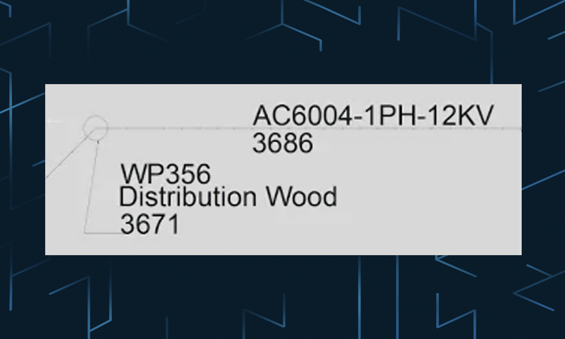
    The data is refreshed and the pole block now contains the Name Number as a label.

    Pic 23 Using Block Attributes to Automatically Label AUD Features

    There are an infinite number of possibilities for labeling in AUD. Using attributes on objects automates the process. You can add as many attributes as you need to any block and they can use a combination of AUD driven values and user updated values. The AutoCAD help file has details on using Attributes. AUD Callouts (Industry Model Callout tab) work in the same way, they just do not have a graphical component like the circle for the pole. You can create custom callouts by starting with the LIN-CALL.dwg and STR-CALL.dwg found in:

    C:\ProgramData\Autodesk\AutoCAD Utility Design 2014\R19.1\enu\Configurations\RUS\Annotations.

  • Callout’s in AUD 2014!

    Callout’s in AUD 2014!

    Have you had a chance to look at AUD 2014? The Callout feature is really nice, very simple, works… and has leaders… and automatic update’s!

    It is simply a block with attributes; you can then define the attribute fields with AUD fields in the editor:

    The only limitation out-of-the-box that I see is it cannot grab data from the material list, so we cannot see the cost or minor materials through the label. Hopefully I am just missing something! I will let you know if I find it.

  • How to set specific layer for AUD Objects – AutoCAD Utility Design 2013

    How to set specific layer for AUD Objects – AutoCAD Utility Design 2013

    In this tutorial we will create a specific layer for the AUD Pole objects, these steps can be used for all AUD objects and will allow the use of traditional AutoCAD Layer commands to control visibility.

    1. Create a new layer called POLES

    a. Type LAYER at the command line to invoke the Layer Properties Manager:

    b. Click the new layer button (in red above).

    c. Type POLES for the layer name:

    d. Close the Layer Properties Manager.

    2. In the Configuration tab in the ribbon click the Industry Model button:

    3. Choose the Pole Feature Class:

    4. Click on the Styles tab:

    Pic 5 How to set specific layer for AUD Objects How t

    5. Click on the Default 2D Plan Symbol, then click the edit button (in red below):

    Pic 6 How to set specific layer for AUD Objects How t

    6. In the Symbol Editor drop down the Layer Name pick list and choose the POLES layer:

    Pic 7 How to set specific layer for AUD Objects How t

    7. Click OK to close the Symbol Editor.

    8. Click Apply to save the changes in the Industry Model Configuration window.

    9. Click OK to close the Industry Model Configuration window.

    10. Select an existing Pole or create and a new one and view its properties (select pole, right-click, choose Properties). You will see the layer is now POLES:

    Pic 8 How to set specific layer for AUD Objects How t

    11. Repeat this process for the Existing and Removal Pole Styles as well or any other AUD object type. You can create layers for each state and then can control AUD Object visibility with traditional AutoCAD layer tools.

  • Adding Pole Heads to an existing pole in AUD

    Adding Pole Heads to an existing pole in AUD

    After you add a Pole in the AutoCAD Utility Design (AUD) environment it is very easy to add most attachments using the tool bars and Design Explorer Pole Heads are one exception to this, they cannot be added using these tools. The command you need is AUDADDTOPOLE. Here is how it works:

    1. Type AUDADDTOPOLE
    2. Type F for Feature
    3. Choose Pole Head
    4. Choose Model Name
    5. Select the Pole Head to use and click OK
    6. Click Back
    7. Click Back
    8. At the command line type X for exit
    9. Select the pole(s) you want to attach to, press enter
    10. Press enter again to end the command

    A little convoluted but it works great! Still working on how to get the conductors to connect and will post as soon as I do. As you can see this tool can be used for all kinds of other attachments as well.

  • Connect to ArcSDE with AutoCAD Map3D, Civil3D, or AutoCAD Utility Design

    Connect to ArcSDE with AutoCAD Map3D, Civil3D, or AutoCAD Utility Design

    Leveraging ESRI ArcSDE in your AutoCAD design can make life a whole lot better! Using the FDO tools found AutoCAD Map3D, Civil3D, and AutoCAD Utility Design this is easy to do. Here are the steps to do it:

    You need these files from an ESRI install (any product):

    1. Pe.dll
    2. Sg.dll
    3. Sde.dll

    You need to copy them into this folder:

    C:\Program Files\Autodesk\AutoCAD *\bin\FDO

    Once you copy them into the folder open AutoCAD *. At the command line type MAPWSPACE and choose Y to open the Task Pane. In the Task Pane click the “Data” button and choose “Connect to Data…”

    Pic 1 Connect to ArcSDE with AutoCAD Map3D, Civil3D, or AutoCAD Utility Des

    In the Data Connections by Provider dialog box choose “Add ArcSDE Connection”, add your connection details and Login with the appropriate username and password:

    Once you have logged in, select your Data Store and Version, click “Connect. The list of layers available to that user are listed, select what is needed and click “Add to Map…”

  • Oracle imp/exp blues…

    Oracle imp/exp blues…

    What a day. Syntax is everything. A file path, that’s all that was missing. So, next time you are importing and Oracle .dmp file (the old style, not the newer dp style) here is the simple syntax:

    imp SYSTEM/password@orcl file=C:\WhereEverYouPutIt\file.dmp full=y log=imp.log

    This did it. It seems that the Oracle imp command does not look in the default DMPDP folder like impdp does.

  • Autodesk Basejump – Bing in your FDO!

    Autodesk Basejump – Bing in your FDO!

    Autodesk Labs released an FDO provider for Map3D and Civil that allows you to use Bing maps as a background!
    It is very cool, but not supported on AutoCAD Utility Design yet, but if you want to use it on AUD install it on Map or Civil3D first and then you can grab the FDO files and copy them to the AUD install. From my testing it seems to work fine, but it is beta product and not supported at all in AUD.
    What you need to do:
    Bing Maps FDO:
    Files to move (also attached) in \bin\FDO:
    BaseMaps_Fragment.xml
    BMSMessage.dll
    BMSProvider.dll
    Project Basejump About Box.txt
    Providers.xml