AUD 7.3 Goes Underground
Latest SBS Release Offers New Advancements in Underground Utility Design
With the recent release of Automated Utility Design™ 7.3 (AUD), SBS continues to push the envelope for modeling and designing distribution utility assets. This post will bring you up to date on the latest enhancements we have made to our underground design functionality.
AUD continues to lead the adoption of 3D modeling in distribution design. We’ve supported electric system modeling for many years, while gas, water and communication have been more recent additions over the past product releases. With multiple clients now leveraging this functionality, we’ve been able to include a number of their wish list of enhancements into this release.
Several of the changes allow for better visualization of underground routing and connectivity, for example, the ability to better model the elevation changes within pipe-based system:
2D Overview
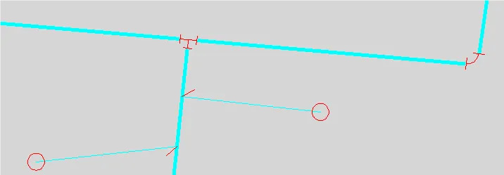
3D Generated Detail Showing Elevation at this same fitting
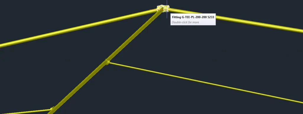
Allowing for features in any discipline (Electric, Gas, Water, Communications, etc.) to be modeled in this manner enables a designer to discover conflicts in congested areas and improve joint trench type designs before they go to the field.
Speaking of conflicts in congested areas – how many times have you wished you could more easily visualize something like this?
A Typical Vault/Duct Arrangement
Well, now you can! Actually, we’ve been able to do this for a while in AUD – but we’ve made it easier and more efficient to manage these kinds of things. Imagine how much more accurate your designs would be if you were able to see this kind of design before you started digging in the ground:
Same Vault and Transformer, in 3D, with Elevation and Conduit/Duct Routing
![]()
“Downtown Underground” is an important topic these days and our users are interested in leveraging every bit of data they collect from the field in this area. We’ve updated AUD to allow for multiple transition points along a bank (e.g. vertical to horizontal orientation, switching the number of conduits, splitting off or joining to other banks). This detail is stored with the design and can be exported to external conduit management systems, like Conduit Manager from Schneider Electric.
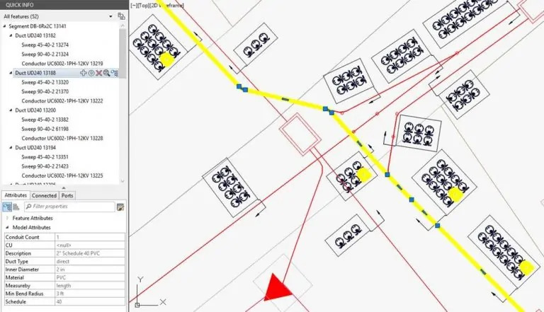
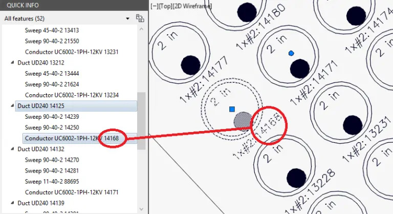
We’ve also added configurable levels of detail inside of our conduits. Duct and conduit symbology can be adapted to your standards, configurable annotations can be automatically generated, assigned and updated – or you can keep it simple and just use AUD to generate standard butterfly diagrams showing populated conduits.
Configurable Level of Detail Inside the Route
If you think you’re seeing a theme with these enhancements, you’d be right! “More Accurate”, “More Efficient”, “Easier to Manage” – these types of changes fit into our corporate vision of “Improving Design Throughput”. By making our software easier and quicker to use while maintaining or improving accuracy, we streamline your design workflows.
As always, we love to hear your thoughts!